English version by Lucien-Paul Kmiotek.
Use the switch position "SIMUL" from the input selector switch to switch on the additional input. With the current version, the recorder must be receiving a television channel through the tuner! Otherwise you will encounter problems with the drum servo. I'm currently working on this problem.
Pos. 3 & 4 is only necessary with S-Video.
The recorder must be dismantled. Take the cover off the function board. Cut the circut at place shown. The recorder on "SIMUL" will now switch to "LINE". (fig. 1)
Now remove the printed circuit of the function board and solder a wire (grey here) about 50cm long long onto the soldered side. The wire has to go to the YC-40 printed circuit. This wire controls the relay. The printed circuit and the cover can now be reassembled. (fig.2)
Now unsolder the middle pin of the video-IN-BNC-socket. Fix a shielded wire onto the middle pin of the BNC socket (RL 8) and in the vacont hole (RL 9) of the YC-40 printet circuit. The shield of both wires must be soldered to the fixture bracket of the socket. (fig. 3)
Remove the audio IN/OUT jack board. There the pin wires 5,6 and 7 must be unsoldered. You now need a 7 pole flat cabel that must be soldered as follows:
The wires to the plug must be insulated. The audio jack board can now be reassembled.
Scart socket: You need a 3 pole flat cable & shielded wire. First solder the three pole cable as follows:
Pos. 5 is only necessary with S-Video.
With S-Video a bridge has to be soldered on the underside of the printed circuit from the scart pin 17 to the pin 13. Also solder the z-diode ZD1 and the resistor R1 through scart pin 13 to 15. Where the black ring of the z-diode points to pin 15. (fig. 6)
Now wire up the relays RL 1: This only works with correct polarization of the voltage supply, check this out first. Solder the diode D1 with the cathode on the plus side and the anode on the minus side. At the same time you can solder the wire from the funktion board (A) and a wire to the minus JW 73. Now cut the 3 pole flat cable from the scart socket to length and shorten the middle wire (orange) by 1 cm. Now solder as follows:
Now cut the 7 pole flat cable from the audio board to length and shorten the middle wire (yellow) by 1 cm. Now solder as follows:
Now cut the shielded wires to length and expose about 1cm. Remove shield and insulate. Solder as follows:
For the s-video version you must convert as follows:
Now to check. If the first attempt is successful you can stick the relay with hot glue. With S-Video the picture at the video and aerial output is black and white while recording. Only during playback and tuner and line operation is the picture at the output still in colour. This problem is difficult to solve. I am working on the S-Video output, maybe this will improve matters.
After this conversion the scart socket ist the same, and can be used with standard cables and adaptors. I have tested the s-video input with the s-video scart adaptor of my camcorder.
With the s-video input and s-video sources (camera, DVD and DVB) the picture is an improvement on standard video input. Cross-colour and cross-luminance, (colours running into one another on striped or checked surfaces) is eliminated. I dont think the s-video input improves the sharpness of the picture though, because the recorder can only reach a maximum of 3,8 MHz (PAL)
I also have a differenet version of the s-video input, that can give a sharper picture. If it works I will let you know.
For navigation please click here.
Circuit diagram: The new parts are red.
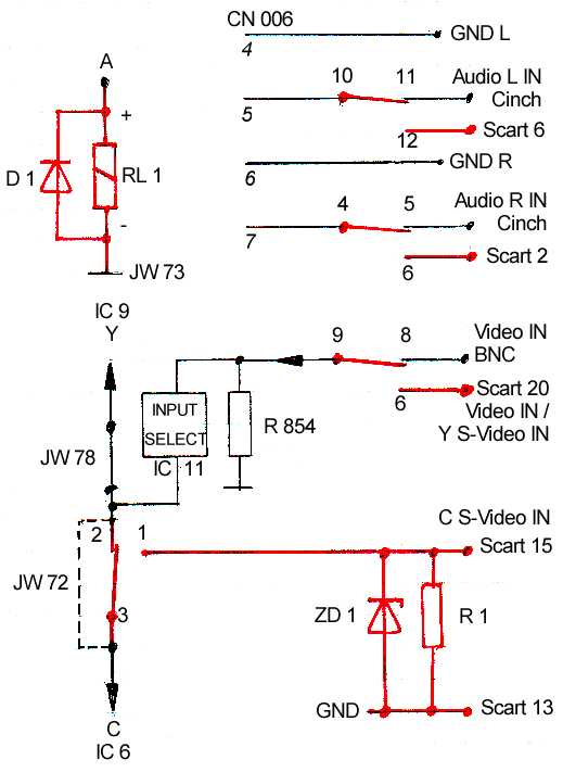
fig. 1: Function board, front.
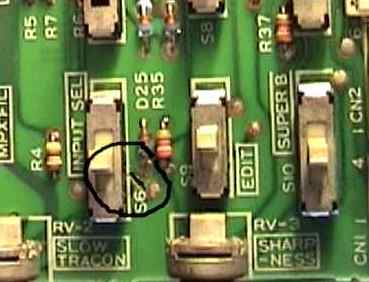
fig. 2: Function Board, back.
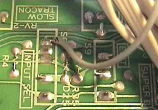
fig. 3: The converted video-in BNC socket in detail.
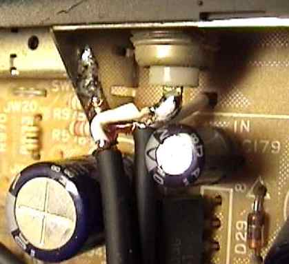
fig. 4: The converted audio jack board.
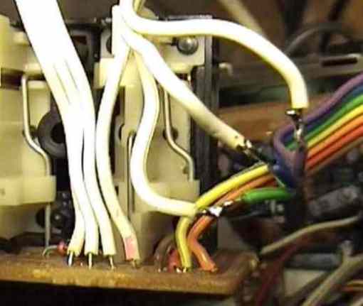
fig. 5: The connection of the scart socket, the shielded wire
on the left is only necessary for the s-video an directs the colour signal (C).
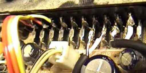
fig. 6: The bridge, 10V z-diode and the 75 Ohm resistor is only necessary for the s-video.
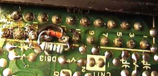
fig. 7: You can see the grey wire of the function board (A) in
the middle. I got the minus pole from the bridge JW73. Above you
can see the 7 pole cable to the audio board, and on the right the
3 pole cable to the scart socket audio in. The numbers on the
relay represent the numbers on the circuit diagram.
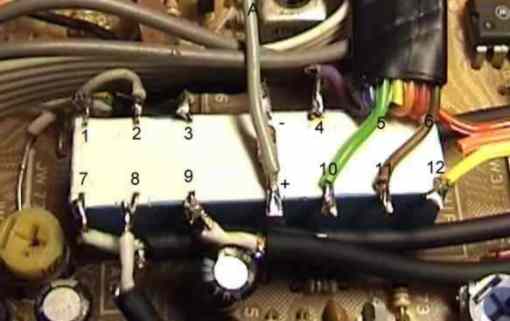
fig. 8: The audio switch-over in detail.
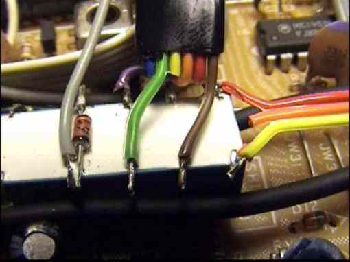
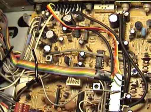
fig. 9 The Y/C-40 printed circuit with relay.